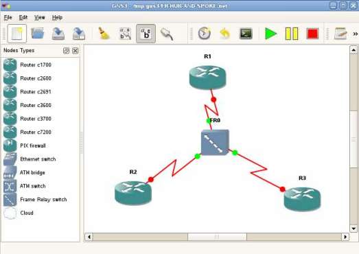
When I first came in touch with GNS3 I had not idea how to work with it. Not because it is so complicate to operate, but because I didn’t saw any software like this one. GNS3 and Dynamips make a very good job together, allowing users to emulate a lot of network scenarios with different topologies. If using only Dynamips suppose that you edit all the configuration file manually in text mode, now with GNS3 you can drag and drop devices, connections and configure them on the fly.
For today, I prepared a presentation about how you can create a Frame-Relay hub and spoke topology in GNS3, save and use it whenever you need it. This tutorial does not include the configuration of the devices which form Frame-Relay hub and spoke, but only the GNS3 lab topology. If you are looking for the tutorial on how to configure FR hub and spoke on Cisco routers, please refer to my previous tutorial.
The GNS3 lab topology which I’ll create in the following presentation is available for download here. Take the saved lab configuration and open it in your GNS3 software. Before you use it, please have a look inside the file, as there are some lines you suppose to modify to fit your system.
Please click on the image below to see the tutorial:


